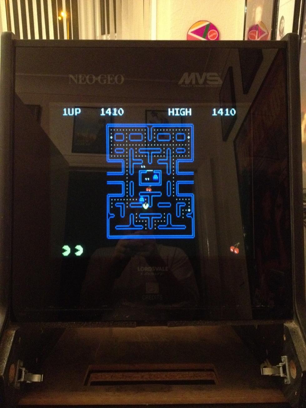
So here is the second cabinet, as it arrived.
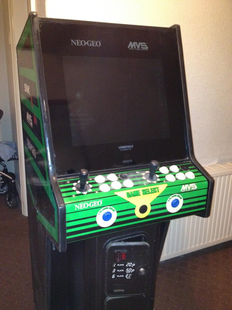
This is one of the NEO-GEO MVS arcade systems, and like the first cabinet, this had seen better days, but was not in quite as bad condition.
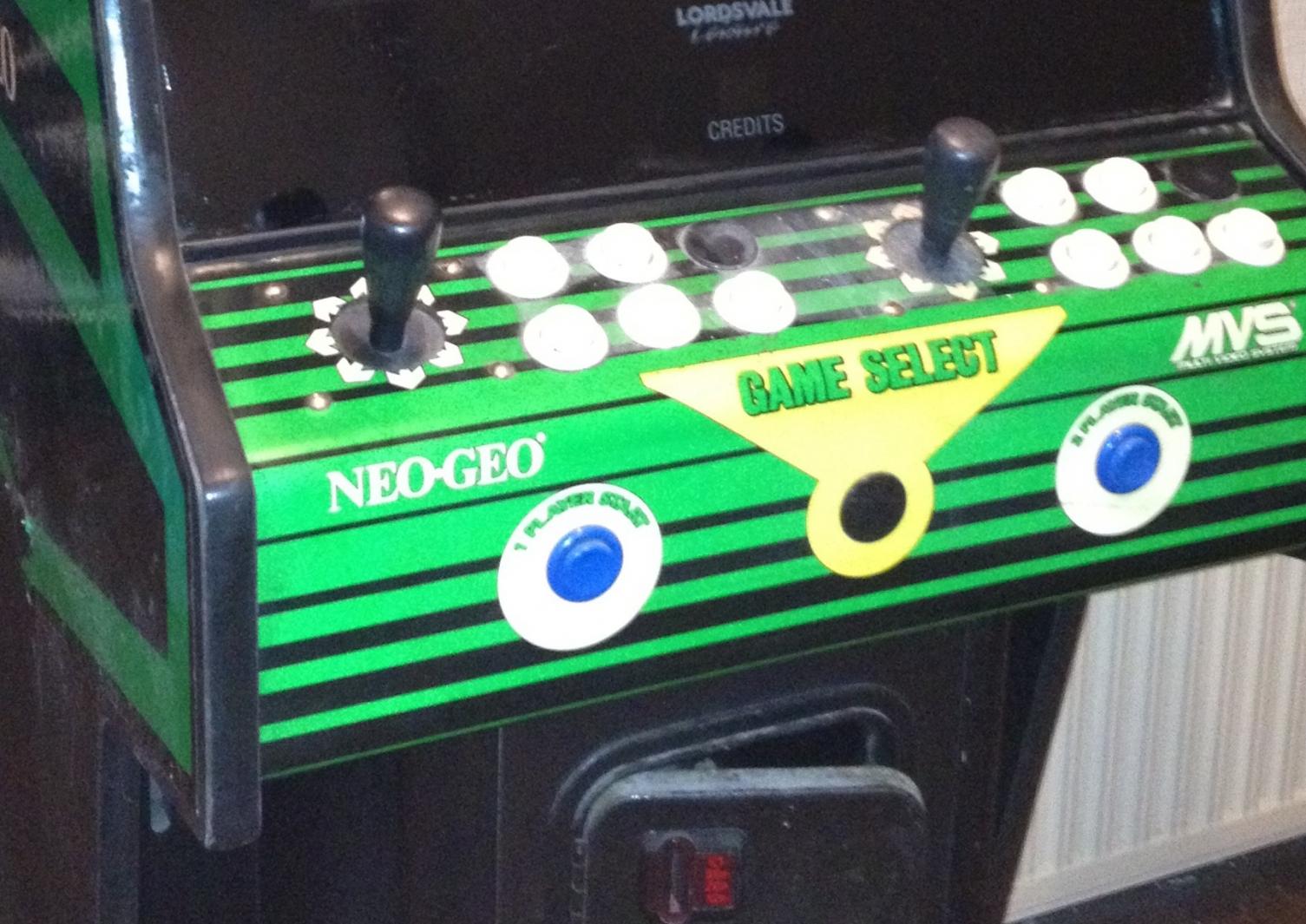
There was a fairly thick layer of dust covering the control panel. The joysticks and buttons were clogged to the point you could barely move them, the side vinyl artwork was damaged and peeling, and some of the metal parts inside had rusted. I wasn’t even going to attempt powering the monitor, as not only are they the 15khz type (and no good for a PC without a special gfx card), there were also cables dangling from the back of it and I was not going to mess with it. I was not bothered in the slightest by any of these things!
CONTROL PANEL
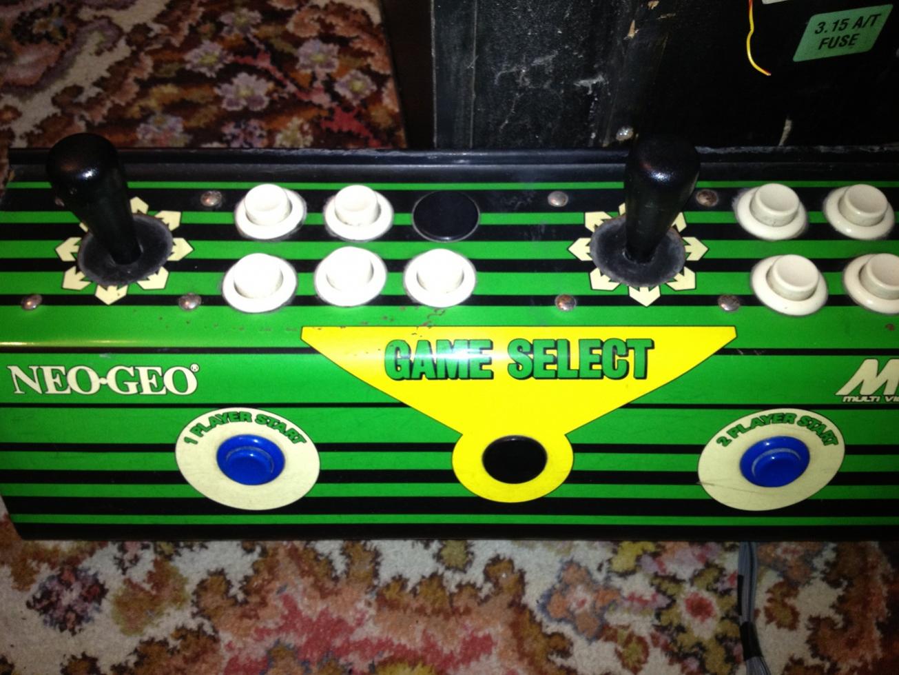
I started by removing the control panel and giving it a complete clean with machine cleaning spray and isopropyl alcohol. While it came up nice and bright, there were cuts around the buttons where I am guessing was scuffing from players nails and/or jewelry. The buttons themselves were not in great shape, I removed them all and took each one apart and washed in soapy water and cleaned and greased the springs. Some of the buttons had what appear to be cigarette burn marks and melted around the edges. The only option was to replace all of the buttons.
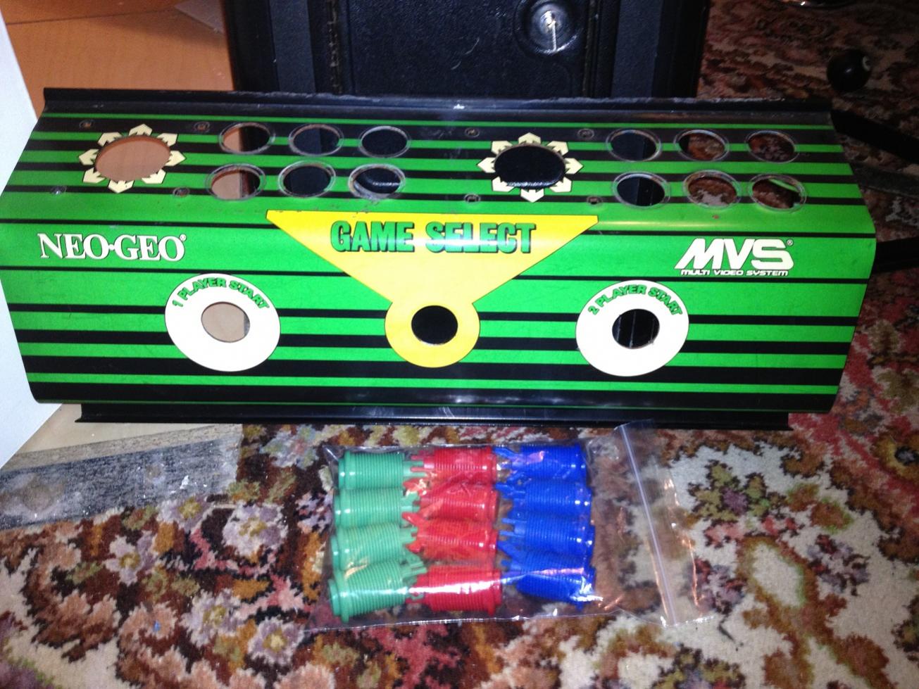
Here is the control panel with the buttons and joysticks removed and a new set of buttons waiting to be installed. But first I had to do something about the old NEO-GEO graphic on the panel. After a lot of um-ing and ah-ing I decided to replace it completely.
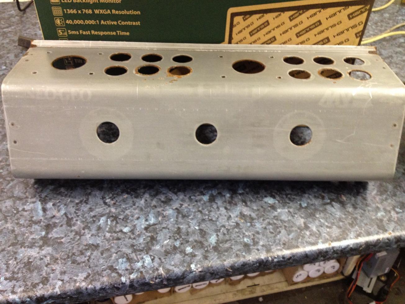
I heated the metal panel up for a while and peeled the whole graphic off. Was left with a LOT of sticky residue underneath which took quite some time to get off! The picture shows the bare panel, the areas around some of the buttons were rusted and rough, so I sanded them down best I could before trying to apply any new graphics.
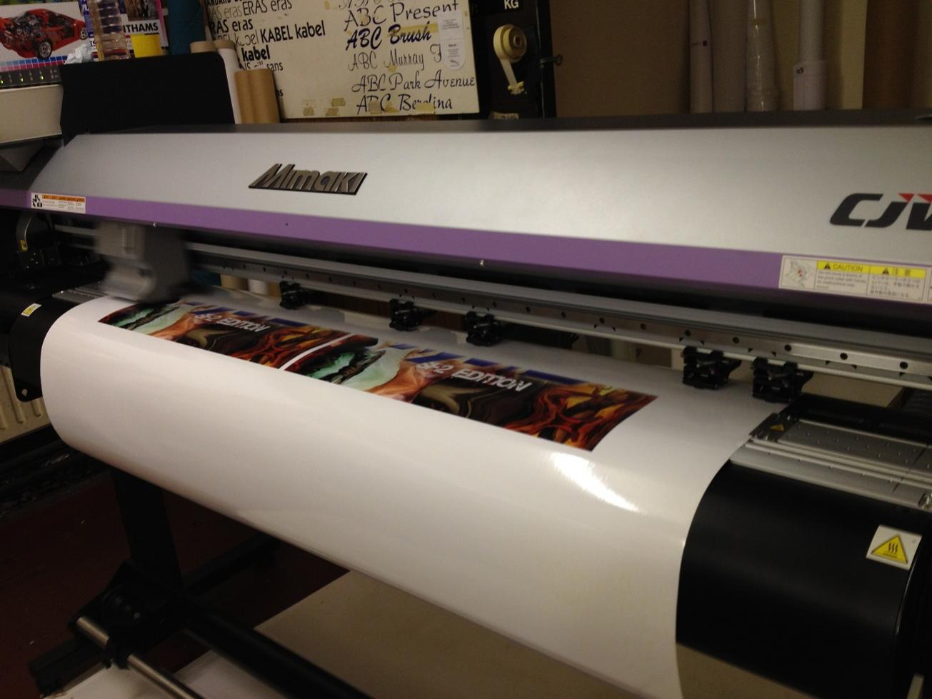
After finding some artwork I felt suited this project (thanks to http://meanlessart.wordpress.com), I was able to call in a favor and get them printed on adhesive vinyl (I had two made in the likely event I messed up the first application)
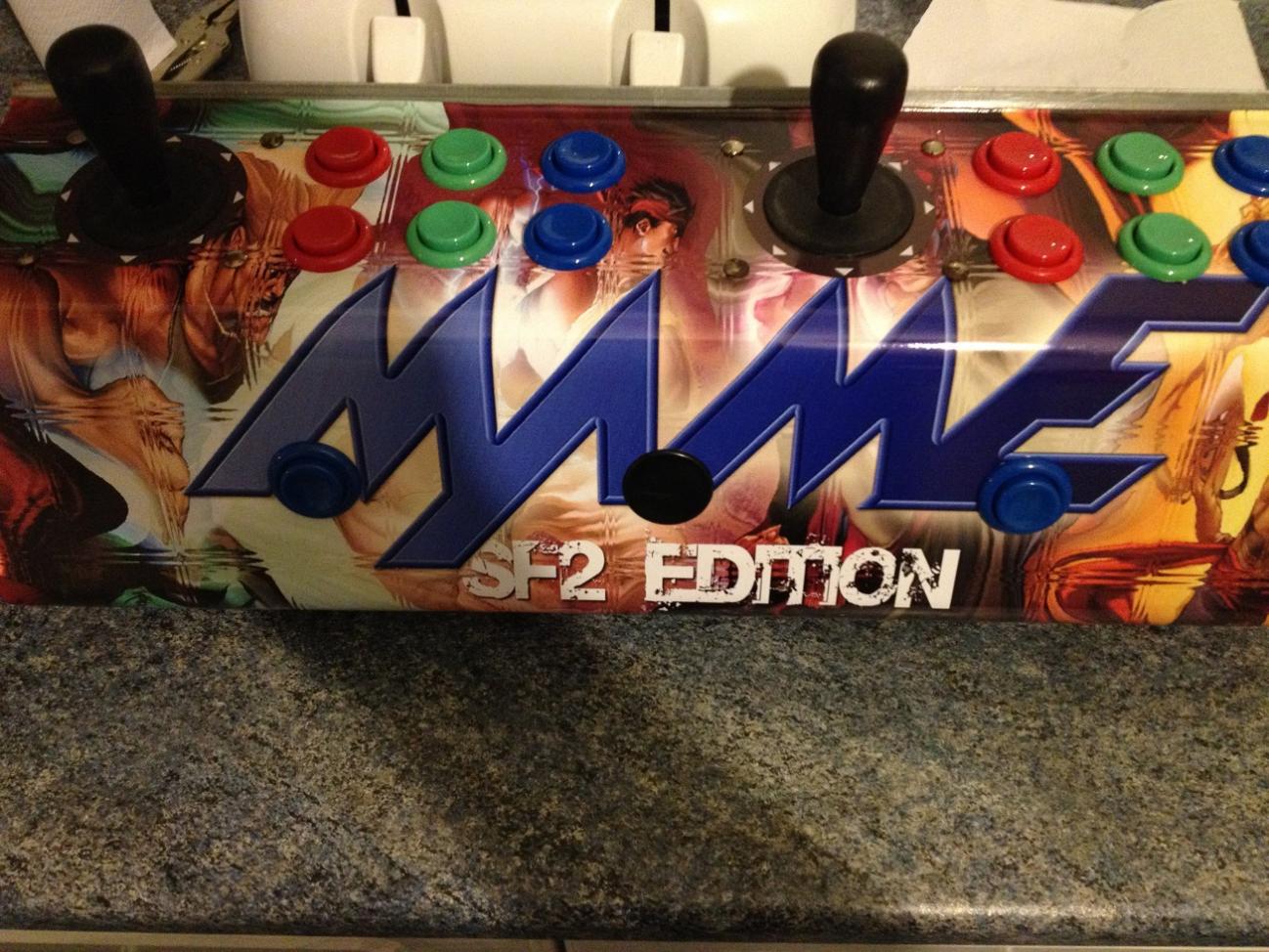
My excitement always gets the better of me and I forget to take enough photos. So here is the control panel with the joysticks and new buttons installed.
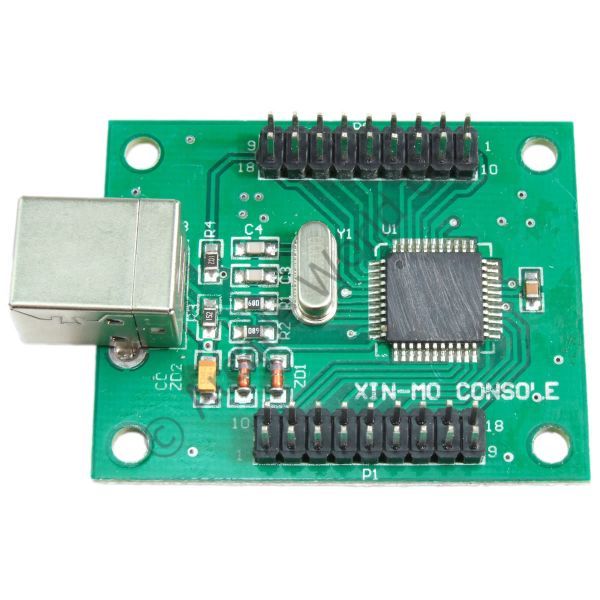
There are many available interfaces to allow microswitch controllers work with PCs under Windows/Linux, the IPAC is a popular choice, but being a cheapskate I went for the this two player USB interface for just over £20. (http://www.arcadeworlduk.com/product…Interface.html)
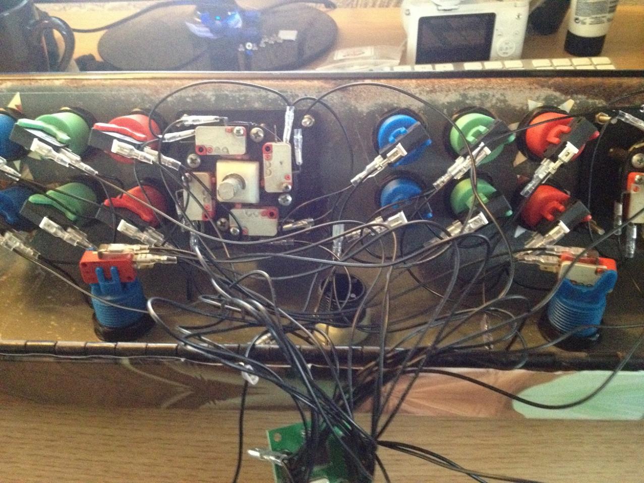
Back view of the control panel with all the wires attached. Yeah I know, spaghetti junction (wires are quite short on these things!)
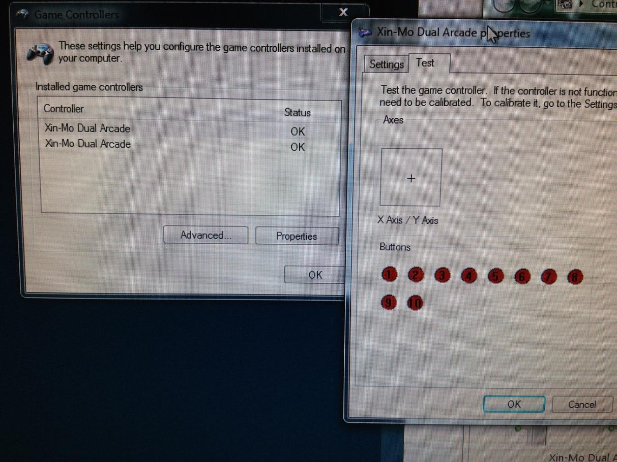
The single USB device identifies to the operating system as two separate joysticks, each with up to 10 buttons. Works with everything that I have tried!
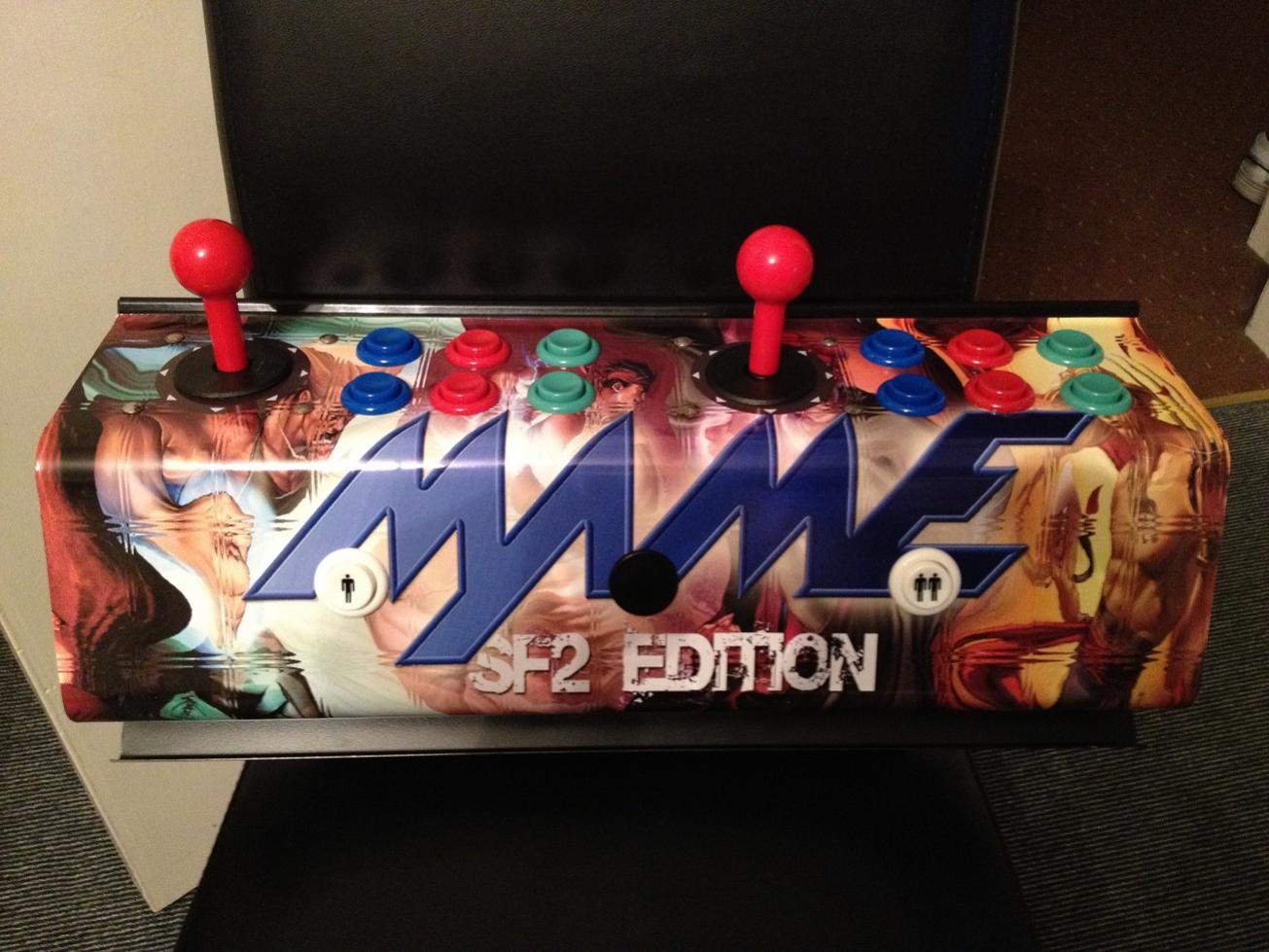
I then decided that since the buttons were all new, that I would replace the joysticks as well, so went with these nice red ones and also replaced the two START buttons with the P1 and P2 logo buttons. (all sourced from www.arcadeworlduk.com).
MONITOR
Next was the monitor, I simply scoured the eBay for 21″ CRT monitors for sale and I got a nice Iiyama one for £20. I had to remove the old mounting fixtures that held the old monitor in place, and built a shelf for this monitor to go on (didn’t take pictures of that part). Once in place I connected it to my laptop and loaded up a YouTube video of Pacman, just to see how it looked! Happy so far!
THE SPINNER
During all this I was thinking about some of the classic arcade games such as Arkanoid and Discs of Tron which require a spinner. There was an available spot in the front middle of the control panel (previously had a blanking button in for some reason, probably used in a different version of the MVS?).
Spinners can be purchased but, did I mention I am a cheapskate?
So looked around for parts to build something of my own. Some people recommend using a jar lid attached to an old ball type mouse photo interruptor, this was not something I liked the sound of since ball type mice are pretty hard to find these days and are usually PS2, which itself is no longer guaranteed on a PC motherboard. After scourging around, I came up with the following:
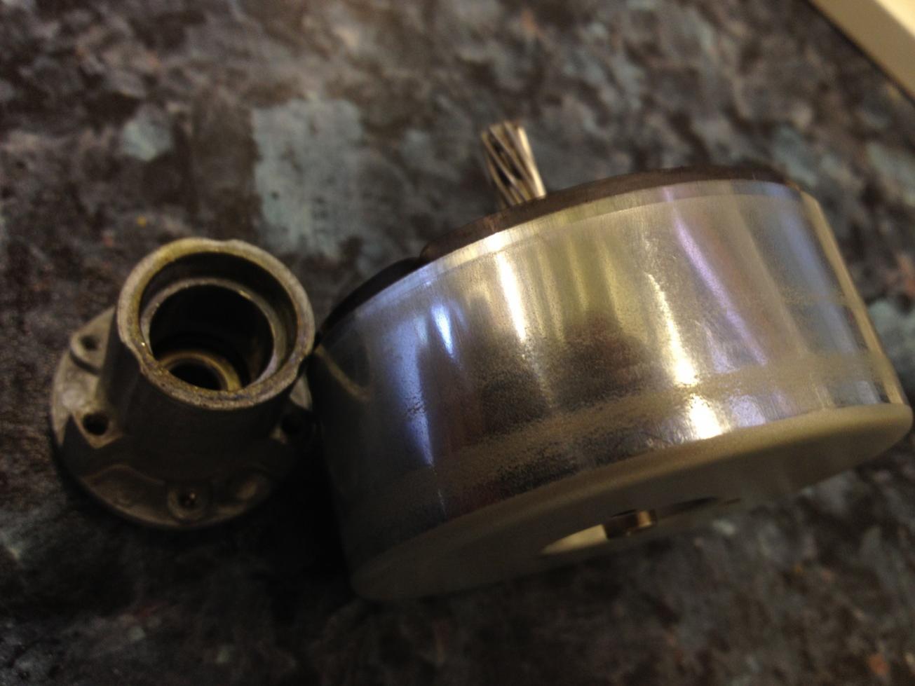
This used to be a part of a 24v stepper motor and its mounting fixture from a laser printer. It had a nice feel due to the heavy magnet inside it, and when sitting in its mount a single spin will keep going for over 10 seconds!
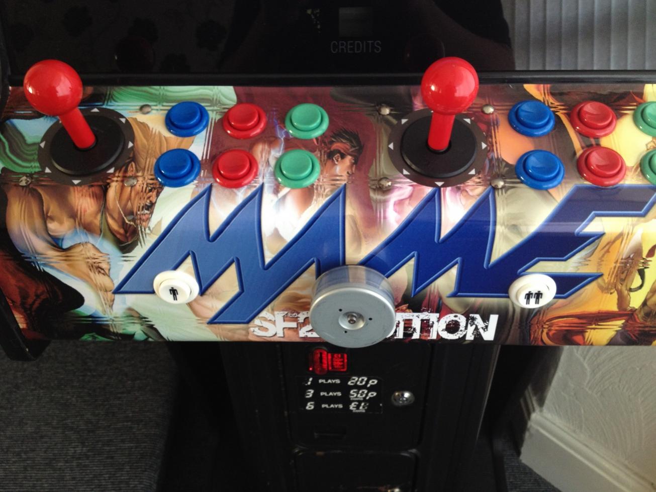 Here is the control panel with the motor part mounted in the front, so I just needed to somehow translate the spinning movement to some type of PC input. Following on from the mouse idea, I picked up a cheap USB optical mouse for £2 and had the idea that if the mouse is held still and something is rotated under the lens, the mouse will interpret that as movement along that axis. I tried it out using a smooth cylindrical piece of plastic from my little boys toybox (nobody seemed to know what it was from) and it worked perfectly. Better than expected in fact, since the optical mouse detects the movement from around 1 mm away from the lens, so it doesn’t touch it at all so there is no friction generated!
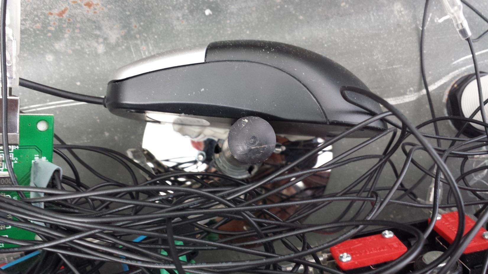
So it was a simple case of a thick glob of glue then standing the mouse in place and maneuvering it slowly while testing the spinner for responsiveness. Once it was in the best location without touching the plastic peg, leaving it overnight to set. After that it was absolutely solid and the spinner worked a treat giving great movement along the mouses Y-axis.
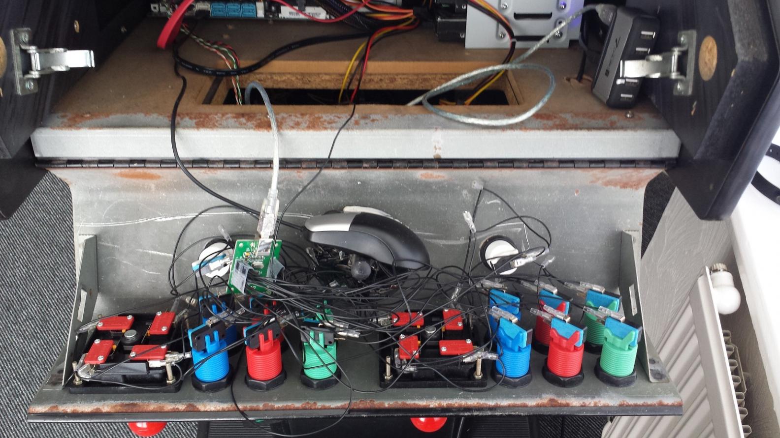
Another picture showing the entire back of the control panel. All the buttons wired to the controller interface and the optical mouse and spinner in place.
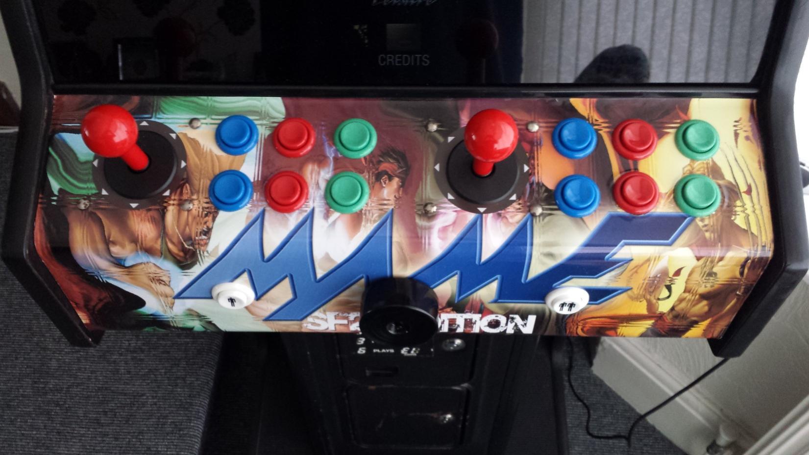
Final look of the control panel now, sprayed the spinner/motor black.
COIN MECHANISM
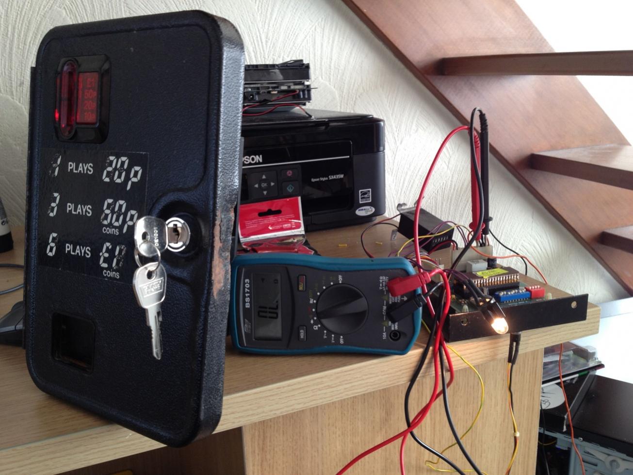 Next I turned my attention to the coin mechanism. I figured since it was there, I wanted it to work! I started by removing the door and entire mechanism and controller PCB from the machine. The bulb didn’t work so replaced that first, the locks were also rusted so changed those too. I then hooked it up to 12v from my PCs PSU while I sussed it out. I had never looked at one before but since there were only three wires coming away from it at the end I kind of narrowed things down like this: one will be GND, one will be 12V, and the other is some sort of output to tell the game a credit has been added. It was a simple case of testing it with the multimeter and sure enough, when a 20p coin goes through the slot, the output wire goes momentarily to GND. When a 50p inserted, the output goes to GND three times consecutively, and £1 six times. This was perfect, as the controller interface has plenty of spare inputs so simply hooked it up to one of them. There is also an “insert coin” button behind the door which allows you to press it to add one credit.
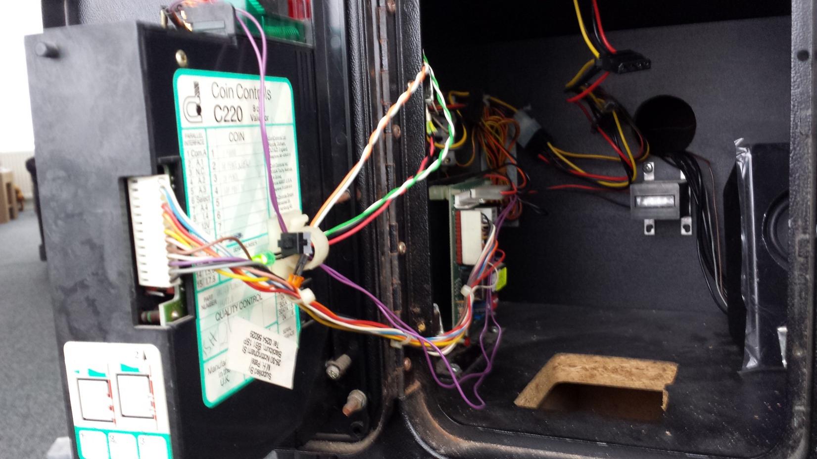
Coin door and mechanism back in place.
THE INTEL INSIDE
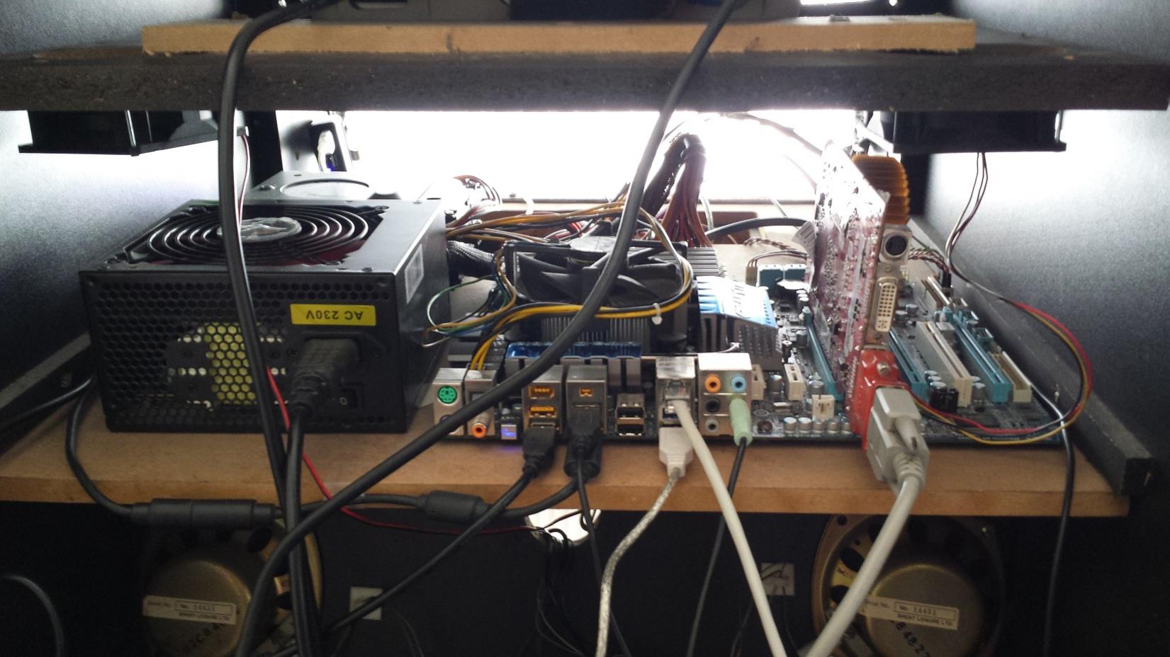
So here are the brains behind it. Installed on the wooden panel is a Gigabyte motherboard (I forget the model, bought it around 2010) with Intel i7-960 3.2Ghz and 12GB DDR3. Luckily I had recently retired this from my main PC when I upgraded it. I also had a spare GeForce GT-9600 which I threw in there. The only part I had to buy was the 700w PSU. I also stuck a few fans too help circulate air in there.
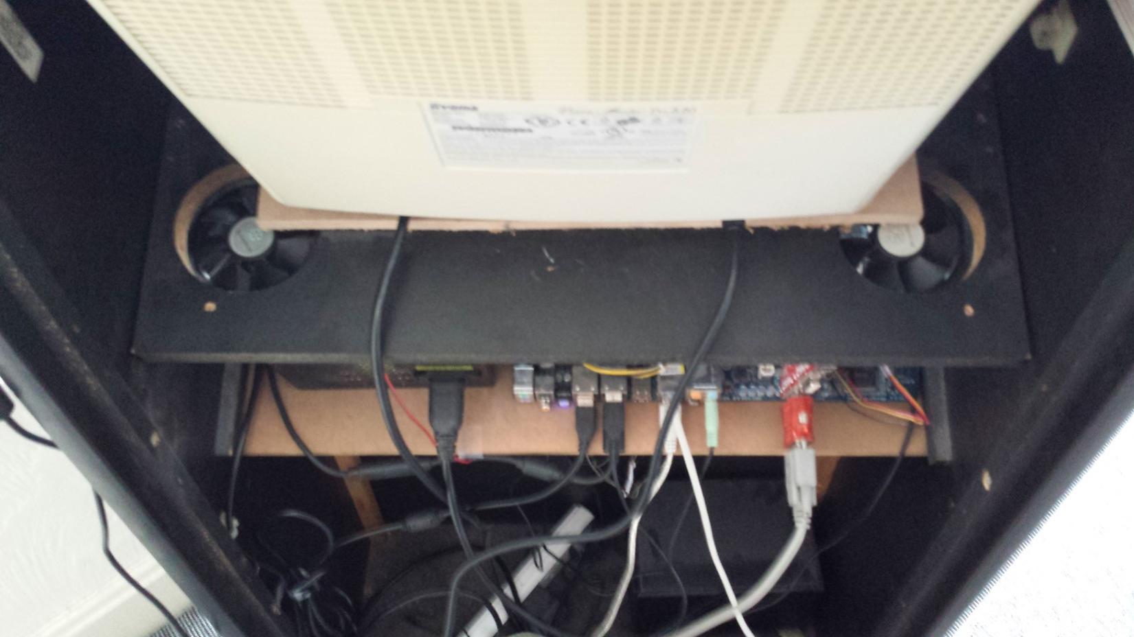
A blurred picture of machine with back off. Notice I added a pair of fans to circulate air around the system.
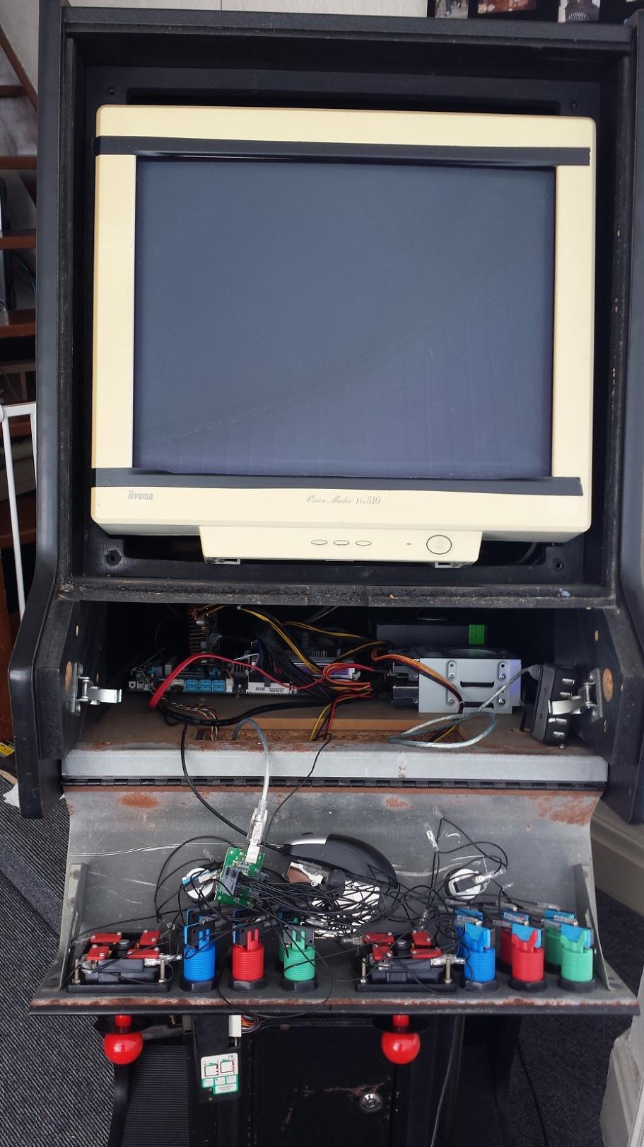
View of front open and glass removed.
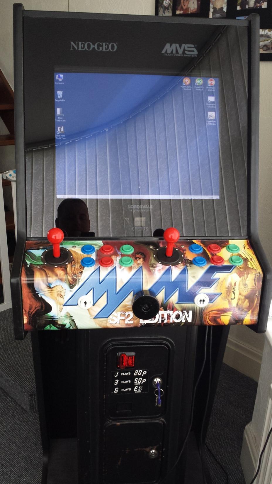
Final look of machine from the front.
LIGHT GUN AND GUITAR
As I am a HUGE fan of the American Laser Games, a light gun was essential for my setup, sadly the only one available was the ACT-LABS ‘Ray-Gun’. The appearance lets it down, however the performance of the pin sharp accuracy during all the light gun games more than compensates for it!
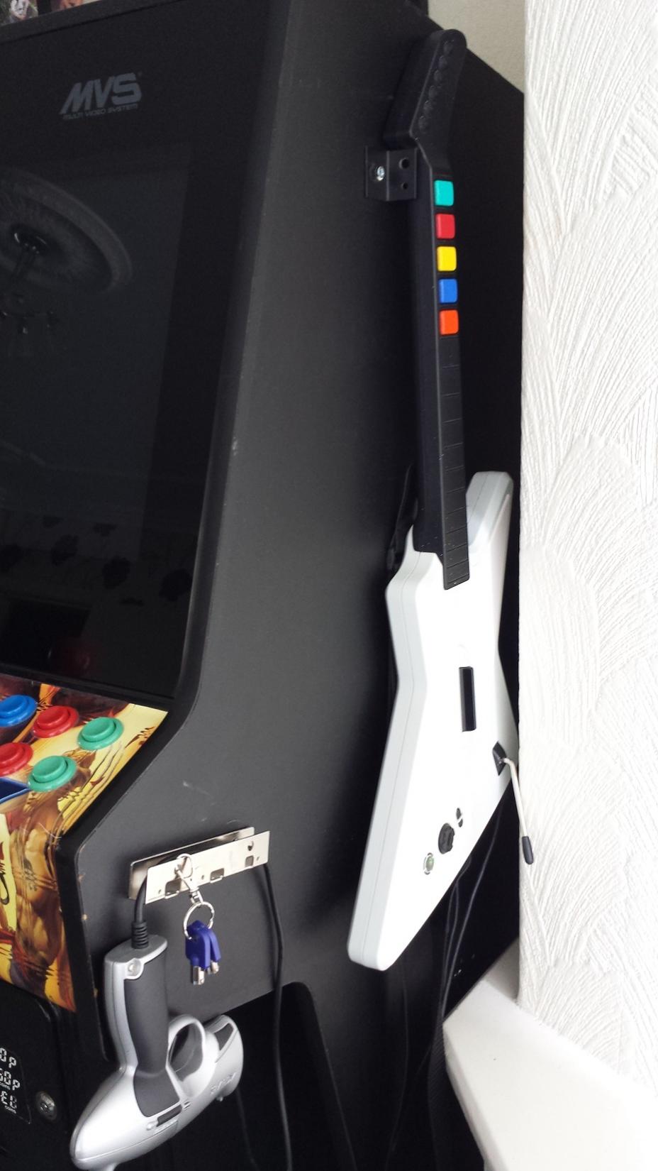
Finally, I couldn’t have an arcade machine without the Guitar Hero and Frets on Fire games, so improvised a bracket to hang my Xbox360 Guitar Controller on the side too!
Well that’s about it for the hardware side! The real hard work started when it came to setting up the software.